

 English
 русский
 Français
 Español
 عربى
عربى
Equipo de incineración de alta temperatura LQ-RTO
Equipo
Descripción general de la torre RTO El oxidante térmico regenerativo (RTO) es un equipo de tratamiento de gas residual orgánico que combina...
Ver detalles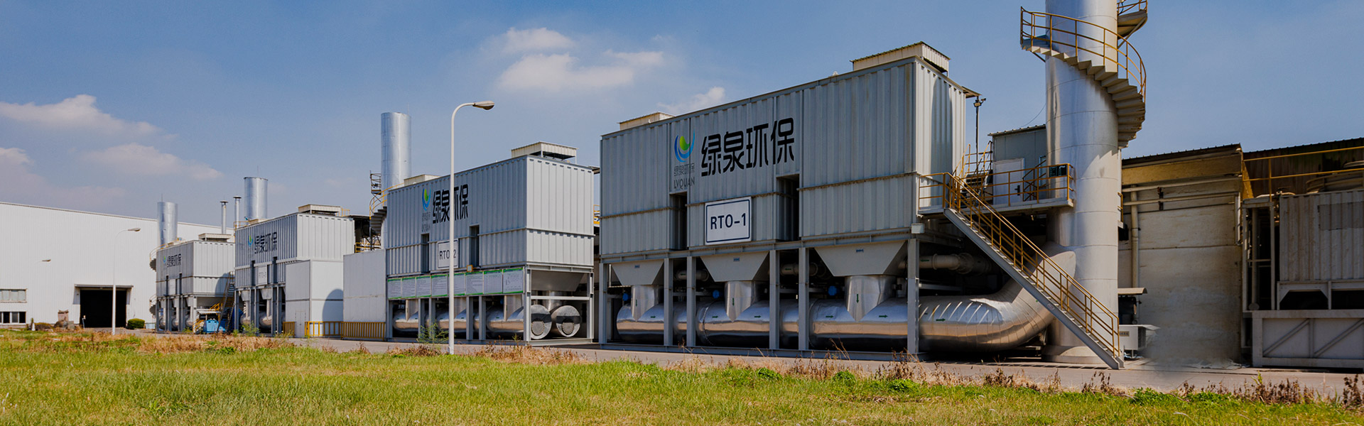
Contenido
el Equipo de incineración de alta temperatura con almacenamiento de calor rotatorio LQ-RRTO logra una eficiencia de eliminación de COV de 95%–99% , combinado con una eficiencia de recuperación de calor superior 95% — lo que la convierte en una de las soluciones de equipos de reducción de COV industriales más eficaces disponibles en la actualidad. A diferencia de los RTO convencionales de tres cámaras, el diseño del oxidador térmico regenerativo rotativo reduce las fluctuaciones de presión de la tubería a tan solo ±50Pa, minimiza las tasas de falla de las válvulas y ofrece un rendimiento constante en el tratamiento de gases residuales orgánicos en una amplia gama de industrias. Para las instalaciones que se ocupan de emisiones de compuestos orgánicos volátiles, este sistema RTO representa un paso adelante mensurable tanto en el cumplimiento ambiental como en la economía energética.
Los sitios industriales en sectores como el petroquímico, farmacéutico, de recubrimientos, de impresión y electrónico enfrentan regulaciones de emisiones de COV cada vez más estrictas. El RTO giratorio, específicamente el LQ-RRTO de Lvquan Protección Ambiental Ingeniería Technology Co., Ltd., aborda estos desafíos combinyo la oxidación a alta temperatura con el almacenamiento de calor cerámico, produciendo CO₂ y agua inofensivos mientras se recicla la energía térmica nuevamente en el proceso. Este artículo desglosa los principios de funcionamiento, los datos de rendimiento y las ventajas reales de esta solución avanzada de tratamiento de COV.
En el núcleo de la Oxidador térmico regenerativo rotativo. Es un ciclo continuo de precalentamiento, oxidación a alta temperatura y recuperación de calor. El LQ-RRTO divide el cuerpo del horno en 12 camas de embalaje de cerámica : 5 cámaras de entrada (zona de precalentamiento), 5 cámaras de salida (zona de enfriamiento), 1 cámara de purga y 1 cámara de aislamiento. El gas residual ingresa a través del distribuidor de admisión, se precalienta mediante cuerpos cerámicos de almacenamiento de calor y asciende a la cámara de combustión donde sufre una descomposición oxidativa completa a temperaturas suficientes para romper los enlaces moleculares de COV.
el purified high-temperature exhaust then moves into the cooling zone, transferring its thermal energy back into the ceramic media. This stored energy preheats the next cycle of incoming waste gas — completing a closed thermal loop. When VOC concentration exceeds a threshold (typically above 500 mg/m³), the oxidation reaction itself releases enough heat to sustain the combustion chamber temperature, eliminando la necesidad de combustible suplementario . Este comportamiento autosostenible es la ventaja definitoria del sistema RTO de ahorro de energía frente a las alternativas de combustión directa (hornos TO).
el rotary valve — a single rotating mechanism replacing the 9 push-cylinder or butterfly valves in traditional three-chamber RTO systems — channels gas alternately through each bed with minimal pressure fluctuation. This design reduces mechanical complexity substantially, lowers maintenance frequency, and extends the operational lifespan of the high temperature incinerator as a whole.
el diagram above illustrates the five-stage flow of the LQ-RRTO: raw VOC-laden waste gas enters the system and is first preheated by ceramic storage beds, which have absorbed heat from the previous exhaust cycle. The preheated gas then enters the central combustion chamber, where organic compounds are oxidized into harmless CO₂ and water at high temperature — achieving a decomposition efficiency of 95% a 99% . El gas limpio y caliente resultante pasa a través de los lechos cerámicos de enfriamiento, depositando energía térmica para el siguiente ciclo de precalentamiento antes de ser descargado como aire limpio compatible. Esta transferencia de energía de circuito cerrado es lo que permite que la eficiencia de recuperación de calor supere el 95%, reduciendo drásticamente el consumo de combustible en comparación con los incineradores de combustión directa. La válvula rotativa en el centro del sistema orquesta silenciosamente este flujo alterno, haciendo que todo el proceso de tratamiento de gases de escape industrial sea fluido, continuo y altamente confiable.
Seleccionar el equipo de reducción de COV adecuado requiere una comparación clara de los parámetros de rendimiento técnico. La siguiente tabla contrasta las tres configuraciones principales de RTO: el RTO tradicional de tres cámaras, el RTO giratorio LQ-RRTO y el RTO monocilíndrico con múltiples válvulas de mariposa. Cada diseño implica compensaciones genuinas entre la complejidad de la válvula, la tasa de purificación, el tamaño y las demandas de mantenimiento.
| Parámetro | RTO de tres cámaras | LQ-RRTO (RTO rotativo) | RTO monocilíndrico y multiválvula |
|---|---|---|---|
| Cámaras de almacenamiento de calor | 3 | 12 | 7 |
| Número de válvulas | 9 | 1 (giratorio) | 21 |
| Tasa de purificación | 99% | 95–99% | 99% |
| Fluctuación de presión | ±250Pa | ±50Pa | ±50 Pa |
| Huella | Grande | Pequeño (compacto) | pequeño |
| elrmal Efficiency | 95% | 95% | 95% |
| Tasa de falla de válvula | Alto | Bajo | Bajo |
el standout figure is the valve count: the LQ-RRTO uses just 1 válvula rotativa en comparación con 9 en el diseño de tres cámaras o 21 en el tipo monocilíndrico multiválvula. Menos piezas móviles se traduce directamente en menos horas de mantenimiento, menor riesgo de tiempo de inactividad y costos de servicio a largo plazo significativamente más bajos para el sistema de tratamiento de gases residuales orgánicos. Para los directores de planta que dan prioridad a la continuidad operativa, esta simplicidad mecánica es un factor decisivo.
Cuantificar el rendimiento del tratamiento de COV de un sistema RTO requiere examinar datos operativos reales en múltiples rangos de concentración e industrias. El LQ-RRTO maneja concentraciones de gases residuales de 500 a 5.000 mg/m³ (equivalente a 2–12 % LEL), que abarca el rango operativo práctico de la mayoría de los procesos industriales de recubrimiento, farmacéuticos y petroquímicos. A continuación se muestra un cuadro que compara la eficiencia de descomposición en varias concentraciones de VOC de entrada.
el chart above reveals a clear positive correlation between inlet VOC concentration and decomposition efficiency in the LQ-RRTO system. At lower concentrations around 500 mg/m³, the system still achieves a strong Tasa de descomposición del 95%. , muy por encima de la mayoría de los umbrales reglamentarios para el tratamiento de gases de escape industriales. A medida que la concentración aumenta hacia los 2500 mg/m³, la reacción térmica autosostenida se vuelve más pronunciada, elevando la eficiencia por encima del 98%, con un rendimiento máximo del 99% en el extremo superior del rango operativo. Este comportamiento es una consecuencia directa del diseño del oxidador térmico regenerativo rotativo: más COV en la corriente entrante significa más energía exotérmica liberada durante la oxidación, lo que eleva y mantiene la temperatura de la cámara de combustión sin combustible auxiliar. Para los operadores de plantas, esto significa que el sistema RTO de ahorro de energía se vuelve progresivamente más rentable a cargas de proceso más altas, convirtiendo lo que de otro modo podría ser un flujo de desechos en un contribuyente térmico neto. El hecho de que la eficiencia nunca caiga por debajo del 95%, incluso en concentraciones bajas, confirma la idoneidad del sistema para entornos industriales de carga variable donde la generación de COV no es constante.
Uno de los argumentos más convincentes para invertir en un sistema RTO avanzado es la reducción acumulativa del costo operativo del combustible. El ciclo térmico autosostenible del LQ-RRTO, combinado con una recuperación de calor del lecho cerámico superior al 95 %, significa que el consumo de combustible cae significativamente después del calentamiento inicial del sistema. El siguiente gráfico de líneas modela la tendencia de consumo de combustible auxiliar de una instalación típica durante un período de 12 meses después de cambiar al RTO rotativo desde un oxidador térmico convencional de fuego directo.
el line chart above compares auxiliary fuel consumption for a representative industrial facility before and after adopting the LQ-RRTO rotary RTO. The upper line (blue) represents a facility using a conventional direct-fired thermal oxidizer — fuel use remains largely stable throughout the year, with only marginal efficiency gains from minor process optimization. The lower line (green) tracks the same facility after switching to the LQ-RRTO: in the first month, fuel use is identical at installation, but drops steeply as the VOC concentration in the waste gas becomes high enough to sustain the combustion chamber temperature independently. Al sexto mes, el consumo de combustible auxiliar de la instalación se había reducido aproximadamente un 75 %. ; al mes 12, la reducción se acercó al 93%. Esta dramática reducción es el resultado cuantificado del ciclo de recuperación de calor >95% exclusivo del sistema RTO de ahorro de energía. En un horizonte de producción de varios años, los ahorros en costos de combustible aumentan sustancialmente, lo que hace que el equipo de tratamiento industrial de VOC no sea simplemente una herramienta de cumplimiento ambiental sino una verdadera inversión de capital con un retorno mensurable. Las instalaciones que procesan corrientes de gases residuales orgánicos de alta concentración suelen tener períodos de recuperación dentro de la vida útil operativa del equipo de 15 a 20 años.
el tratamiento de gases de escape industriales Los requisitos varían considerablemente entre sectores. El equipo de incineración de alta temperatura con almacenamiento de calor rotatorio LQ-RRTO se ha implementado en una amplia gama de industrias, cada una con distintas composiciones de VOC, rangos de concentración y marcos de cumplimiento distintos. A continuación se muestra un gráfico de barras horizontales que muestra la proporción del total de unidades LQ-RRTO instaladas por industria, según la cartera de implementación de Lvquan.
el horizontal bar chart above illustrates how broadly the LQ-RRTO and its VOC abatement equipment platform have been adopted across industrial sectors. The coating and painting industry accounts for the largest share at 24% de la base instalada, impulsado por procesos con alto contenido de solventes en aplicaciones de recubrimiento de bobinas y automóviles, donde las continuas emisiones de COV de alto volumen hacen que un sistema RTO de ahorro de energía sea económicamente atractivo. Las operaciones petroquímicas representan 20% de implementaciones, seguido por la fabricación de productos farmacéuticos y químicos en 17% — sectores con composiciones complejas y a menudo variables de gases residuales que requieren capacidades sólidas de tratamiento de gases residuales orgánicos. Impresión ( 15% ) y electrónica ( 12% ) completan la mayor parte de la cartera. La diversidad de industrias atendidas refleja la adaptabilidad del LQ-RRTO: al ajustar las dimensiones del lecho cerámico, la velocidad de rotación y el tamaño de la cámara de combustión, el sistema puede diseñarse para manejar todo, desde solventes de impresión con alto contenido de tolueno hasta compuestos halogenados mixtos comunes en la fabricación de productos electrónicos. Para los gases residuales corrosivos que contienen azufre o cloro, Lvquan especifica SUS2205 o materiales resistentes a la corrosión de grado superior, una consideración de ingeniería crítica que a menudo se pasa por alto en la adquisición de tratamientos genéricos de gases de escape industriales. Esta amplitud del sector no es accidental; refleja más de una década de ingeniería de aplicaciones acumulada en el programa de fabricación y servicio posventa de Lvquan.
Elegir entre RTO rotativo, oxidación catalítica, adsorción con carbón activado y TO de combustión directa implica equilibrar múltiples dimensiones de rendimiento simultáneamente. El gráfico de radar a continuación compara el LQ-RRTO con dos enfoques alternativos comunes en seis ejes de desempeño clave: eficiencia de eliminación de COV, recuperación de energía, complejidad del mantenimiento, eficiencia de la huella, costo de capital inicial (puntuado de manera inversa: mayor significa menor costo) y flexibilidad operativa.
el radar diagram makes clear why the LQ-RRTO stands out as a comprehensive industrial VOC treatment equipment platform. Across the six performance dimensions examined, the rotary RTO occupies the largest total polygon area — meaning it delivers the most balanced high performance across all evaluated criteria simultaneously. Its Puntuación de eficiencia de eliminación de COV del 99 % and Puntuación de recuperación de energía del 97%. son los más altos de cualquier tecnología comparada, lo que refleja el doble beneficio de la combustión completa y el reciclaje continuo del calor del lecho cerámico. La oxidación catalítica (línea discontinua naranja) tiene un rendimiento competitivo en flexibilidad operativa y simplicidad de mantenimiento, pero se queda corta en recuperación de energía, ya que los catalizadores no almacenan ni devuelven calor como lo hacen los lechos de relleno cerámico. La adsorción de carbón activado (línea de puntos violeta) obtiene la puntuación más alta en términos de bajo costo de capital y es ventajosa en escenarios ligeramente regulados o de baja concentración, pero su eficiencia de eliminación de COV de aproximadamente el 80 % y su recuperación de energía casi nula la hacen inadecuada para procesos de alto rendimiento bajo estrictos mandatos de emisiones. En términos de eficiencia de espacio, el LQ-RRTO obtiene una puntuación del 92 %, superando al RTO de tres cámaras al que reemplaza y comparable al tipo de válvula múltiple de un solo cilindro, gracias a la carcasa compacta de la válvula rotativa. Cuando los administradores de instalaciones deben elegir una plataforma de equipos de reducción de COV para un horizonte operativo de 10 años, el perfil de radar del LQ-RRTO presenta un caso convincente: ningún eje es débil, y las dimensiones de mayor riesgo (eficiencia de eliminación, recuperación de energía) son precisamente donde sobresale.
El tratamiento eficaz de los gases residuales orgánicos comienza con la selección adecuada del sistema. El LQ-RRTO está diseñado para manejar una amplia variedad de perfiles de gases residuales, pero ciertas condiciones del proceso requieren adaptaciones de ingeniería específicas. Los siguientes criterios deben guiar las decisiones de adquisición:
else criteria underscore the importance of accurate waste gas characterization before equipment selection. Lvquan's engineering team provides process gas analysis support as part of its project development service, ensuring the specified LQ-RRTO configuration matches the actual VOC composition, flow rate, and regulatory requirements of each installation site.
Lvquan Environmental Protection Engineering Technology Co., Ltd. está ubicada en la ciudad de Gaoyou, Yangzhou, la "puerta norte" de la provincia de Jiangsu, China. Fundada como una sociedad anónima por profesionales con más de 30 años de experiencia combinada En el diseño y fabricación de equipos de COV, Lvquan se ha establecido como uno de los principales fabricantes especializados de equipos de ingeniería de tratamiento de gases residuales orgánicos de China.
el company holds a registered capital of 22 millones de yuanes , con activos fijos acercándose 40 millones de yuanes y activos totales de casi 60 millones de yuanes . Sus instalaciones de producción de 9.800 m² están equipadas con más de 200 juegos de equipos de mecanizado. y atendido por 120 empleados , soportando una capacidad de producción anual de 100 millones de yuanes . Lvquan posee la calificación de Gobernanza y Diseño de Contaminación Ambiental de la provincia de Jiangsu, está reconocida como una empresa de alta tecnología de Jiangsu y ha superado con éxito las certificaciones de sistemas ISO9001 e ISO14001.
el company currently holds 13 patentes de modelos de utilidad and 2 patentes de invención de alta tecnología y es una unidad miembro designada de la Asociación de la Industria de Protección Ambiental de Jiangsu. Siguiendo los principios de "enfoque, tecnología, calidad, servicio y satisfacción", Lvquan integra tecnologías internacionales avanzadas de adsorción e incineración en equipos fabricados en el país que cumplen o superan los parámetros de referencia de los productos importados, lo que hace que los equipos industriales de tratamiento de VOC sean accesibles a una gama más amplia de fabricantes chinos e internacionales que buscan una gestión eficiente y compatible de los gases de escape.
el LQ-RRTO achieves a decomposition efficiency of 95% a 99% en todo su rango de concentración operativa estándar de 500 a 5000 mg/m³. La eficiencia de recuperación de calor supera el 95 %, lo que reduce significativamente la demanda de combustible auxiliar en funcionamiento continuo.
el key difference is valve architecture. The LQ-RRTO uses a single rotary valve to control gas flow across 12 ceramic beds, compared to 9 switching valves in a three-chamber design. This reduces pressure fluctuation from ±250 Pa to ±50 Pa, lowers valve failure rates substantially, and reduces the total system footprint — while maintaining equivalent thermal efficiency.
Sí. Para gases residuales que contienen componentes corrosivos como azufre, cloro u otros COV halogenados, Lvquan especifica acero inoxidable dúplex SUS2205 o materiales resistentes a la corrosión de mayor calidad para los componentes internos relevantes. Esto debe declararse explícitamente durante el proceso de selección del equipo para garantizar que se incorporen en el diseño las especificaciones de materiales adecuadas.
Las corrientes de gases residuales que contienen partículas de polvo, niebla de aceite o residuos pegajosos deben someterse a un tratamiento previo (por ejemplo, separación ciclónica, filtración con bolsas o precipitación electrostática) antes de ingresar al RTO giratorio. Estos contaminantes pueden causar bloqueo del lecho cerámico o eventos de recalentamiento. Además, las concentraciones de gases residuales superiores a 1/4 LEL requieren dilución antes de su entrada para mantener condiciones operativas seguras.
el LQ-RRTO can be configured with low-NOx combustion systems for regions with NOx emission limits. Where the waste gas itself contains elevated nitrogen components, supplementary post-combustion DeNOx treatment may be required in addition to the low-NOx burner. NOx requirements should be specified clearly during system selection so the appropriate combustion design is applied.
el LQ-RRTO is suitable for a wide range of industries generating VOC-containing exhaust, including petrochemicals, pharmaceuticals, chemical manufacturing, automotive coating, coil coating, wire enameling, printing, electronics, furniture production, and building materials manufacturing. The system accommodates concentration ranges of 500–5,000 mg/m³ and can be engineered for specific VOC compound profiles encountered in each sector.
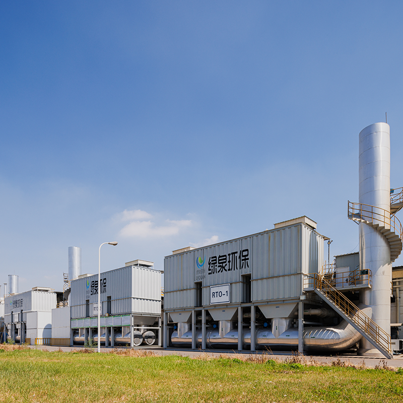
Descripción general de la torre RTO El oxidante térmico regenerativo (RTO) es un equipo de tratamiento de gas residual orgánico que combina...
Ver detalles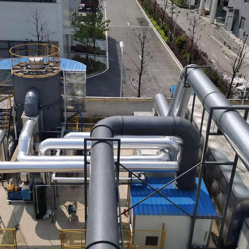
Descripción general de la torre RTO Nuestra compañía ofrece dos tipos de RTO rotativo, que son el RTO rotativo y el RTO de válvula múltiple...
Ver detalles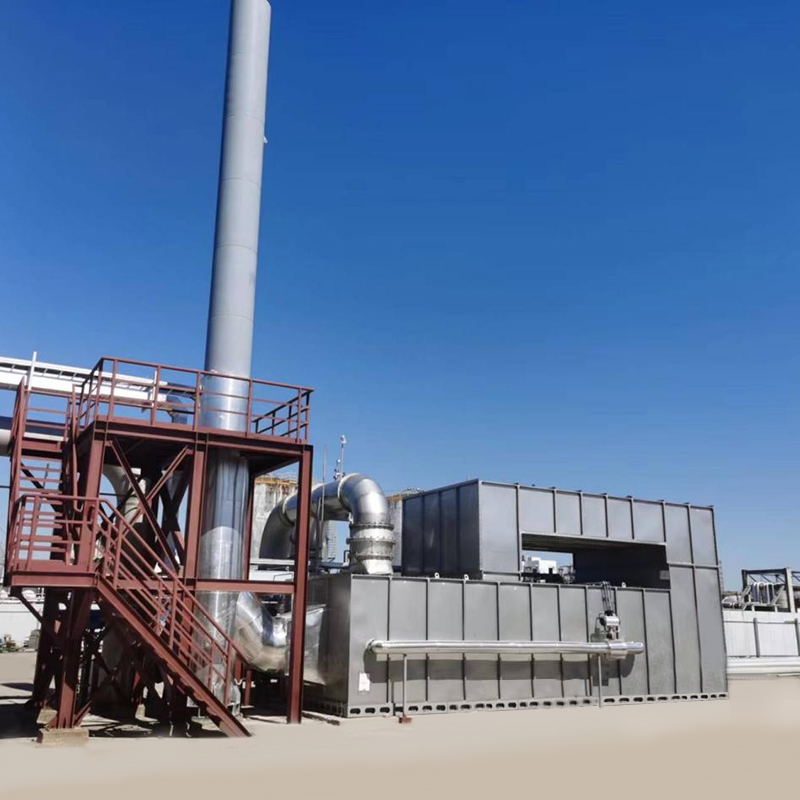
Descripción general La combustión catalítica es un método de purificación que utiliza catalizadores para oxidar y descomponer sustancias co...
Ver detalles
Descripción general La serie VOC-ACA Equipo de purificación de carbono y recuperación de partículas orgánicas de gases se utiliza para la a...
Ver detalles
Introducción al producto El intercambiador de calor de gas se utiliza principalmente para las industrias de ahorro de energía y reducción d...
Ver detalles
Descripción general Los hornos de incineración de residuos sólidos son equipos esenciales en la gestión de residuos sólidos, diseñados ...
Ver detalles
Concepto del sistema RTO de la rueda de zeolita Utilizando la rueda de zeolita para adsorbar el gas residual orgánico, la baja concentració...
Ver detalles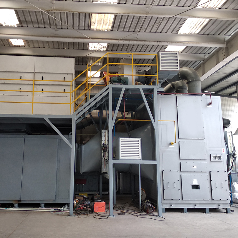
El concepto del conjunto completo de equipos El propósito de emplear la adsorción de zeolita de tambor giratorio para el gas de residuos or...
Ver detalles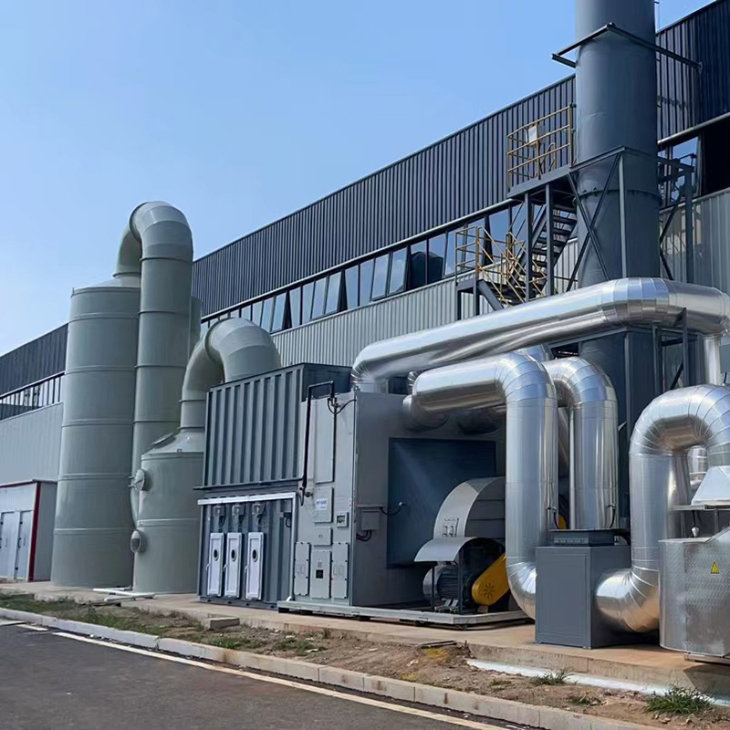
Concepto de combustión catalítica de zeolita de lecho fijo como un conjunto de equipos El dispositivo de combustión catalítica de zeolita d...
Ver detalles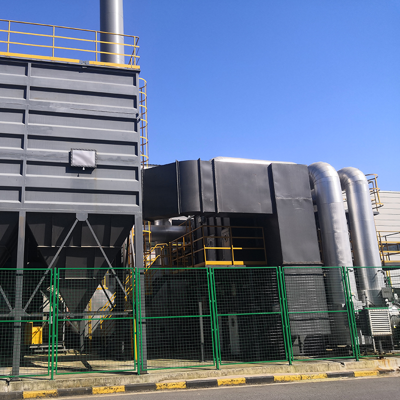
El concepto de equipo de incineración de alta temperatura de la rueda de zeolita El propósito de emplear la adsorción de zeolita de tambor ...
Ver detallesMÓVIL
Instrucciones del producto

Derecho de Autor © LV Quan Environmental Protection Engineering Technology Co., Ltd. Todos los Derechos Reservados
