Para COV de baja concentración (por debajo de 1.000 mg/m³) , la adsorción con carbón activado es la opción más económica. Para concentraciones medias (1.000–3.000 mg/m³) , la combustión catalítica (CO) ofrece una eficiencia óptima. Para Corrientes de alta concentración superiores a 3.000 mg/m³ o mezclas complejas. Los oxidantes térmicos regenerativos (RTO) ofrecen una eficiencia de destrucción superior al 99 %.
El criterio de selección fundamental es el límite inferior de explosividad (LEL). Cuyo la concentración de COV excede 25% LIE , RTO se vuelve obligatorio para el cumplimiento de la seguridad. Por debajo de este umbral, los costos operativos y los requisitos de eficiencia de destrucción determinan la tecnología óptima.
Diferencias principales entre las tres tecnologías centrales
Adsorción de carbón activado
Esta tecnología opera mediante adsorción física, capturando moléculas de VOC en superficies porosas de carbono. Destaca en el manejo Corrientes intermitentes de baja concentración (50–1000 mg/m³) con costos de capital iniciales 40-60% menos que los sistemas de oxidación térmica. Sin embargo, genera residuos secundarios (carbono gastado que requiere eliminación o regeneración) y no puede manejar eficazmente corrientes con mucha humedad o cargadas de partículas.
Combustión Catalítica (CO)
Los sistemas catalíticos utilizan catalizadores de metales preciosos (normalmente platino o paladio) para oxidar los COV a 300–500°C , significativamente menor que la oxidación térmica. Esto reduce el consumo de combustible en 60–80% en comparación con la combustión directa. Ideal para operaciones continuas con flujos consistentes de concentración media. La desactivación de catalizadores de compuestos de silicio, azufre o halógenos representa el principal riesgo operativo.
Oxidante Térmico Regenerativo (RTO)
Los RTO alcanzan una eficiencia térmica de hasta 95–97% mediante intercambiadores de calor cerámicos que recuperan el calor de la combustión. Las temperaturas de funcionamiento oscilan entre 760–1100°C , asegurando una oxidación completa incluso con mezclas complejas de COV. Si bien la inversión de capital es la más alta ( $150,000–$500,000 para unidades estándar), los costos operativos disminuyen a concentraciones más altas debido a la operación autotérmica, donde la combustión de COV sostiene el proceso sin combustible suplementario.
Análisis comparativo de tecnologías de tratamiento de COV | Parámetro | Carbón activado | Combustión Catalítica | RTO |
| Concentración óptima | < 1.000 mg/m³ | 1.000–3.000 mg/m³ | > 3.000 mg/m³ |
| Temperatura de funcionamiento | ambiente | 300–500°C | 760–1100°C |
| Eficiencia de destrucción | 90–95% | 95–99% | 99–99,9% |
| Costo de capital relativo | Bajo (1,0x) | Medio (2,5x) | Alto (3,5x) |
| Residuos Secundarios | Carbono gastado | Ninguno | Ninguno |
Parámetros críticos para la selección de equipos
Características de los COV
La estructura molecular de los COV afecta directamente la viabilidad del tratamiento. Compuestos que contienen cloro, azufre o silicio envenenará los catalizadores en los sistemas de CO dentro 200–500 horas de funcionamiento . El benceno, el tolueno y el xileno (BTX) responden excelentemente a la oxidación térmica, mientras que los compuestos oxigenados como la acetona requieren tiempos de residencia más altos. Los hidrocarburos halogenados necesitan depuradores postratamiento para eliminar los gases ácidos formados durante la combustión.
Caudal y variabilidad
La capacidad de diseño debe adaptarse a los caudales máximos con una 15-20 % de margen de seguridad . Los sistemas RTO toleran variaciones de flujo de ±20 % sin una pérdida significativa de eficiencia, mientras que los sistemas catalíticos requieren un flujo estable para una recuperación óptima del calor. Los lechos de carbón activado enfrentan riesgos de canalización cuando los caudales caen por debajo 60% de la capacidad de diseño .
Contenido de partículas y humedad
Las corrientes de entrada deben contener menos de 5 mg/m³ de partículas and por debajo del 50% de humedad relativa para sistemas de adsorción de carbono. Los RTO pueden manejar hasta 30 mg/m³ de partículas pero requieren prefiltración para cargas más altas. Contenido de humedad arriba 15% en volumen reduce significativamente la capacidad de adsorción y puede requerir una deshumidificación aguas arriba.
Requisitos reglamentarios
Los límites de emisiones locales dictan los requisitos de eficiencia de destrucción. En los Estados Unidos, los estándares de Tecnología de Control Máximo Alcanzable (MACT) de la EPA a menudo requieren 99% de eficiencia de destrucción , exigiendo RTO o sistemas de CO de alto rendimiento. Los umbrales de la Directiva Europea sobre Emisiones Industriales (IED) varían según el compuesto, con límites para el benceno en 5 mg/m³ y VOC totales en 20 mg/m³ .
Mal funcionamiento común y solución de problemas
Fallas del sistema de carbón activado
Emisiones innovadoras ocurren cuando el carbono alcanza la saturación, detectable cuando las concentraciones de salida exceden 10% de los niveles de entrada . Esto suele ocurrir después 2000 a 8000 horas dependiendo de la carga de COV. Incendios en la cama resultan de la adsorción exotérmica de cetonas o de un enfriamiento inadecuado; temperaturas superiores 150°C en el lecho de carbón indican un riesgo inminente de combustión.
Problemas de combustión catalítica
La desactivación del catalizador se manifiesta como crecientes concentraciones de salida or aumento de las temperaturas de funcionamiento requeridas . Un aumento de temperatura de 50°C por encima del valor inicial indica una pérdida de actividad del catalizador del 30 %. El choque térmico debido a cambios rápidos de temperatura (>100°C/hora) provoca el colapso de la estructura de soporte del catalizador. Los precalentadores no alcanzan 350°C mínimo provocar una oxidación incompleta y una acumulación peligrosa de COV.
Problemas operativos de RTO
Taponamiento de medios cerámicos reduce la eficiencia térmica por debajo 85% , detectable por el aumento del consumo de combustible. La caída de presión a través del intercambiador de calor no debe exceder 15 pulgadas de columna de agua ; los valores más altos indican bloqueo. Fallas en el sello de la válvula causar contaminación cruzada entre la entrada y la salida, reduciendo la eficiencia de destrucción aparente mientras se mantienen las temperaturas de la cámara de combustión.
Indicadores de diagnóstico y umbrales críticos | Mal funcionamiento | Señal de advertencia | Umbral crítico | Acción inmediata |
| Fuego en lecho de carbón | Temperatura creciente del lecho | > 150°C | Purga de nitrógeno de emergencia |
| Envenenamiento por catalizador | Aumento de COV en la salida | > Salida 50 ppm | Reemplace el lecho del catalizador |
| Conexión de medios RTO | Caída de presión alta | > 15 pulgadas H₂O | Limpieza/reemplazo de medios |
| Oxidación insuficiente | Baja temperatura de la cámara | < 760°C (RTO) | Aumentar el consumo de combustible |
Protocolos de mantenimiento de rutina
Inspecciones diarias
Los operadores deben verificar diferenciales de presión de entrada y salida , registre las temperaturas de la cámara de combustión e inspeccione los componentes visibles en busca de fugas o corrosión. Para los sistemas de carbono, el monitoreo diario de sistemas de detección innovadores es obligatorio. Todas las lecturas deben desviarse menos de 5% desde el inicio valores establecidos durante la puesta en servicio.
Trámites Semanales
- Calibre analizadores de COV utilizando gases de referencia certificados
- Inspeccionar las correas del ventilador, los cojinetes y los consumos de amperaje del motor.
- Verifique los interbloqueos de seguridad y los sistemas de apagado de emergencia.
- Verificar la calibración del monitor LEL y los tiempos de respuesta
- Drene el condensado de los conductos de entrada y de las carcasas de los filtros.
Mantenimiento mensual
Realizar inspecciones detalladas de actuadores y sellos de válvulas en sistemas RTO: reemplace los sellos que muestren un desgaste superior 2mm . Para unidades catalíticas, inspeccione los precalentadores en busca de puntos calientes que indiquen falla del elemento. Los sistemas de carbono requieren muestreo de cama determinar la capacidad de adsorción restante; números de yodo a continuación 600 mg/g indicar la necesidad de reemplazo.
Revisiones trimestrales y anuales
Las actividades trimestrales incluyen inspección completa de los medios en unidades RTO, pruebas de actividad catalítica en sistemas de CO y reemplazo de carbono para sistemas de adsorción que procesan compuestos de alto peso molecular. El mantenimiento anual incluye inspección refractaria y ajuste del quemador para una óptima 3% de exceso de oxígeno y verificación integral del sistema de control. Presupuesto aproximadamente 8-12% del costo de capital inicial anualmente para materiales y mano de obra de mantenimiento.
Preguntas frecuentes
¿Se pueden combinar múltiples tecnologías de tratamiento de COV?
Sí. Sistemas híbridos concentrador-RTO Utilice ruedas de zeolita o carbono para concentrar corrientes con bajo contenido de COV (50–500 mg/m³) mediante Proporciones de 10:1 a 20:1 antes de la oxidación térmica. Esta configuración reduce el consumo de combustible RTO en 70-90% en comparación con el tratamiento directo de corrientes diluidas. De manera similar, la adsorción de carbono con regeneración de vapor que alimenta la combustión catalítica maneja picos intermitentes de alta concentración.
¿Cuál es el período de recuperación típico para el RTO versus la combustión catalítica?
En concentraciones de COV superiores 2.500 mg/m³ , los sistemas RTO logran una recuperación de la inversión dentro de 18 a 30 meses mediante el ahorro de combustible a pesar de los mayores costos de capital. La combustión catalítica ofrece una recuperación de la inversión más rápida ( 12 a 18 meses ) en concentraciones medias donde la longevidad del catalizador excede 3 años . Abajo 1.500 mg/m³ , el carbón activado sigue siendo el más rentable en un ciclo de vida de 10 años .
¿Cómo manejo las concentraciones variables de COV de los procesos por lotes?
Instalar tanques de compensación o recipientes de compensación para amortiguar los picos de concentración. Para sistemas RTO, implementar bypass de gas caliente para ventilar el exceso de calor cuando las concentraciones exceden las condiciones autotérmicas. Los sistemas catalíticos requieren inyección de aire de dilución para mantener las concentraciones de entrada por debajo 25% LIE . Los sistemas de carbón activado toleran mejor la variación, pero requieren camas de gran tamaño para manejar cargas máximas sin avance.
¿Existen alternativas para los COV halogenados que no pueden utilizar catalizadores estándar?
Los compuestos halogenados requieren Oxidadores térmicos con torres de enfriamiento y depuradores de gases ácidos. . Los RTO se pueden adaptar con medios cerámicos resistentes a la corrosión y depuradores cáusticos aguas abajo para eliminar HCl o HF. Alternativamente, oxidantes térmicos recuperativos (no regenerativos) ofrecen una integración más sencilla con sistemas de fregado húmedo para aplicaciones a pequeña escala.
¿Qué sistemas de seguridad son obligatorios para los equipos de tratamiento de COV?
Todos los sistemas de oxidación térmica requieren Monitores LEL con cortes automáticos de combustible at 25% LIE (o 50 % con controles con clasificación SIL ). Los apagados por alta temperatura se activan en 1.200°C para RTO. Los sistemas de carbono necesitan detectores de monóxido de carbono en los espacios de cabeza de los buques y sistemas de purga de nitrógeno para la extinción de incendios. Los respiraderos de emergencia deben manejar 150% del flujo máximo anticipado .
 English
 русский
 Français
 Español
 عربى
عربى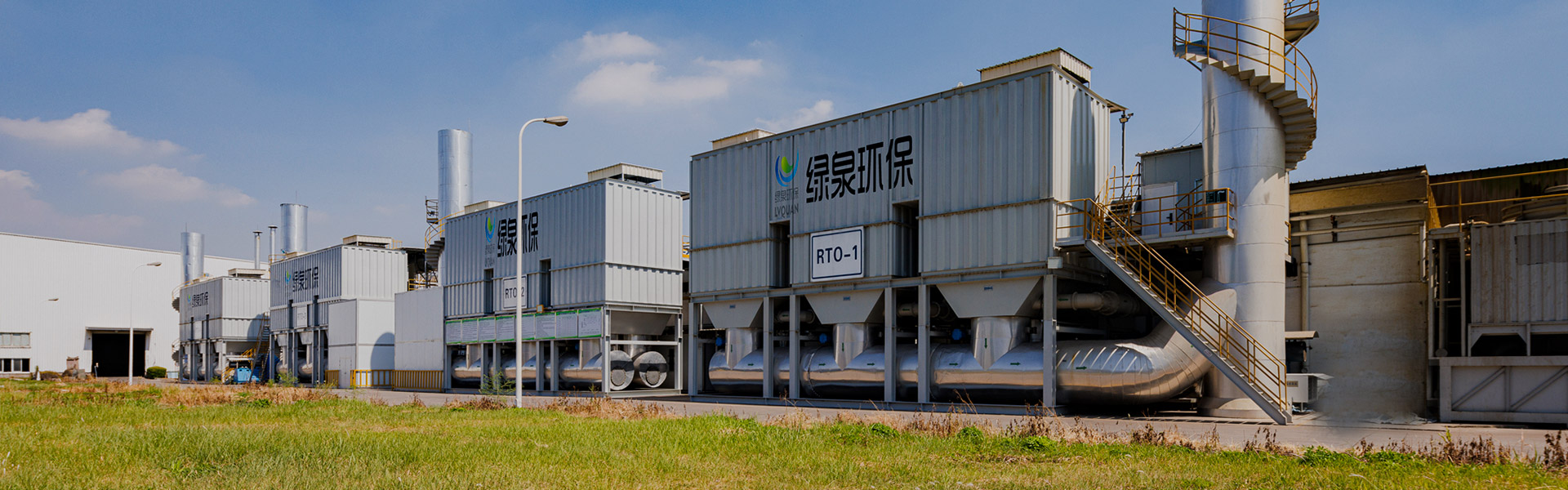


")


 + oxidante térmico regenerativo (RTO)")
")
")
 + Oxidación catalítica (CO)")